We are trying to using Skydel software and USRP N310 to simulate the GNSS reflectometry scenarios. It means that two antennas are mounted on the Vehicle. Antenna 1 will face up to receive the GNSS Light of Sight signal then output to RF 0 port of USRP N310. Antenna 2 will face down to receive the GNSS reflected signal and output to RF 1 of USRP N310.
Do you think this experimental scenario is possible by Skydel and USRP N310? Your advice or recommendation would be really helpful for us.
Thank you for your answering our question in advance.
In order to perform this scenario, you need to run 2 instances of Skydel software. Each instance will simulate one antenna. The 2 instances can be on the same simulator (using SKY-MULTI license) or on 2 different and synchronized (using common 1PPS and 10 MHz signals) simulators. Each instance must use different radios.
Furthermore, on the first instance you could simulate the LOS only, and on the second instance you could deactivate the LOS and only simulate one echo with the correct parameters.
Phu - To add to what Pierre-Marie said, you can verify that you have multi-instance enabled in your software by going to the Help Menu at the top of the software and clicking on “About Skydel”. Here , you should hopefully have a number next to Multi-Instance of at least “2”. This means that you can open the software 2 times and configure each instance seperatley.
Thank you very much for your kind explanation. Our Skydel Multi-instance is 4 and we are going to proceed the method that you advised. Hopefully, we can get the useful experimental result.
In your suggestion of using Multi-instance, we need to use two different radios. Unfortunately, our laboratory only have one N310 SDR. We have been thinking a potential method to work around, using the same SDR
Experiment 1: Streaming the IQ base-band signal to the SDR in Light of Sight configuration and record the RF signal (direct transmission from satellite)
Experiment 2: Streaming the same IQ base-band signal to the SDR in multi-path configuration (LOS deactivated) and record the RF signal (reflected)
Develop the method to process direct RF and reflected RF signals to work out the altimetry of the Vehicle
Our main concern is the synchronization issue of the two experiments when we run them at different time moments, although we use the same IQ data stream
Do you think our proposed method is do-able? If not, it would be very helpful to have your recommendation for another method.
With only one radio your method can work with the following considerations:
Instead of playing and recording the RF signal you can simply use the IQ File license to directly record the baseband signal in a file. It is much simpler and eliminates any synchronization issue (the IQ files will start exactly at the same time).
Play back the IQ Files with 2 transmitters using Advanced Jamming option. The 2 signals can be simulated on a single RF output, or on 2 different RF outputs of your radio (depending if you want to combine the RF signals or not). You can use Simplified Transmitters in Skydel if you don’t want to simulate any propagation effect (other than what you have recorded in the IQ Files).
Let me know if it is clear and if this solution works for you.
Thank you very much for your suggestion. I am going to set up the experiment based on your proposed method and run it on Monday. Will get you updated about the result.
@rburke We are from the Australian Centre for Space Engineering Research (ACSER), University of New South Wales, Sydney, Australia. We would be thankful to have your support.
We followed your advice to generate two IQ files, one for direct Light of Sight signal (no echo), another is for multipath echo. We streamed one or these two IQ files into one or two different RF outputs of N310. However, we received the error message “Unable to use iq file…ip”: sampling rate mismatch. We reckoned the error is something relevant to the mismatching of sampling rates between the generated .ip file and the operating sampling rate of the transmitter. But we are not sure how to fix it and get it working?
Our another question is that when we generated two .ip files (one for direct Light of Sight without echo, another is with only echo no Light of Sight), how to we generate them exactly the same length to be used in GNSS-R scenarios?
When you generate the IQ File, you can choose the sampling rate of the output file. You have to select the same sampling rate than the sampling you are going to use on the radio to playback the IQ File (with a transmitter).
Thank you very much for the explanation. I followed your suggestions can generate two .ip files ok. Now we come to another issue.
Between our two generated baseband data iq files, one is from the direct Light of Sight (no multi-path echo), another is from multipath echo (LOS de-activated) with pseudo range at 1000m. We need to develop the algorithm to work out the altimetry of the SV, i.e., the height of the SV from the earth surface at the reflection point. To do this task, we need to know the location (x,y,z co-ordination) of the satellite and the SV. Can you please explain us how to get these information?
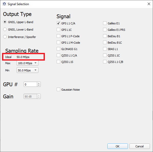
An additional question is that from the sampling rate selection screen as you shown, we can choose the Max and Min sampling rate. What is the actual sampling rate of the IQ data in the .iq file and how do we know it?
You can log the raw data of the simulation (with the position of the receiver and satellites) by checking “Raw logging (csv)” in the Global → Logging menu.
The actual sampling rate is indicated in the radio configuration:
Thank you very much for your helpful answer. I now have following questions and would be thankful if you answer them.
have you got an idea how to use MATLAB to read sample-by-sample the IQ data saved in .iq file in computer by Skydel?
I generated two IQ files 30-sec each, same sampling rate 12.5MSps, one of them is in Light of Sight condition (LOS, no echo) and another is in Echo condition (no LOS). I expected both files have exactly same size as they have same number of samples. However, on the hard-disk, the size of the LOS IQ file is 1,470,459 KB while that of echo file is 1,471,338 KB. Have you got an idea how this can be?
Also, I expect the size of each 30-sec IQ file is 3012.510^62/2^10 = 7.324210^5 KB which is not the size on disk. Could you please clarify on this?
I know this is an old thread, but I will give an answer in case someone stumble upon this.
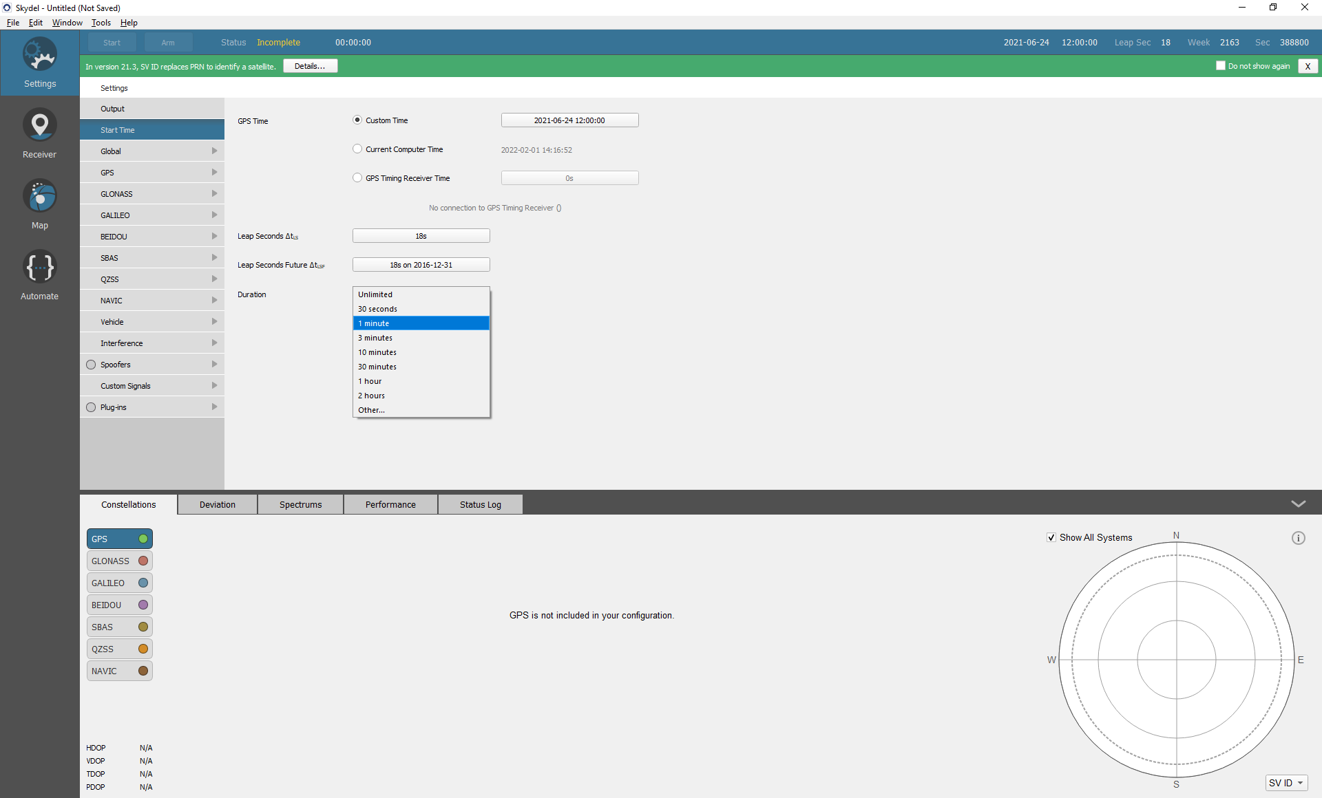
The Skydel stop sequence is currently non-deterministic, but you will always at least simulate the duration you asked.
IQ files are 32 bits (4 bytes, 2 bytes I and 2 bytes Q), you can work out where to crop the file with this formula.